Optimization View Modes
Note: The book is a work in progress. This page serves as a placeholder for the future content.
Let me show you some optimization view modes. In the upper left corner, press “Lit” go to “Optimization Viewmodes” and here we have them. These are our basic tools to check some performance issues before we proceed with the actual profiling.
Light Complexity
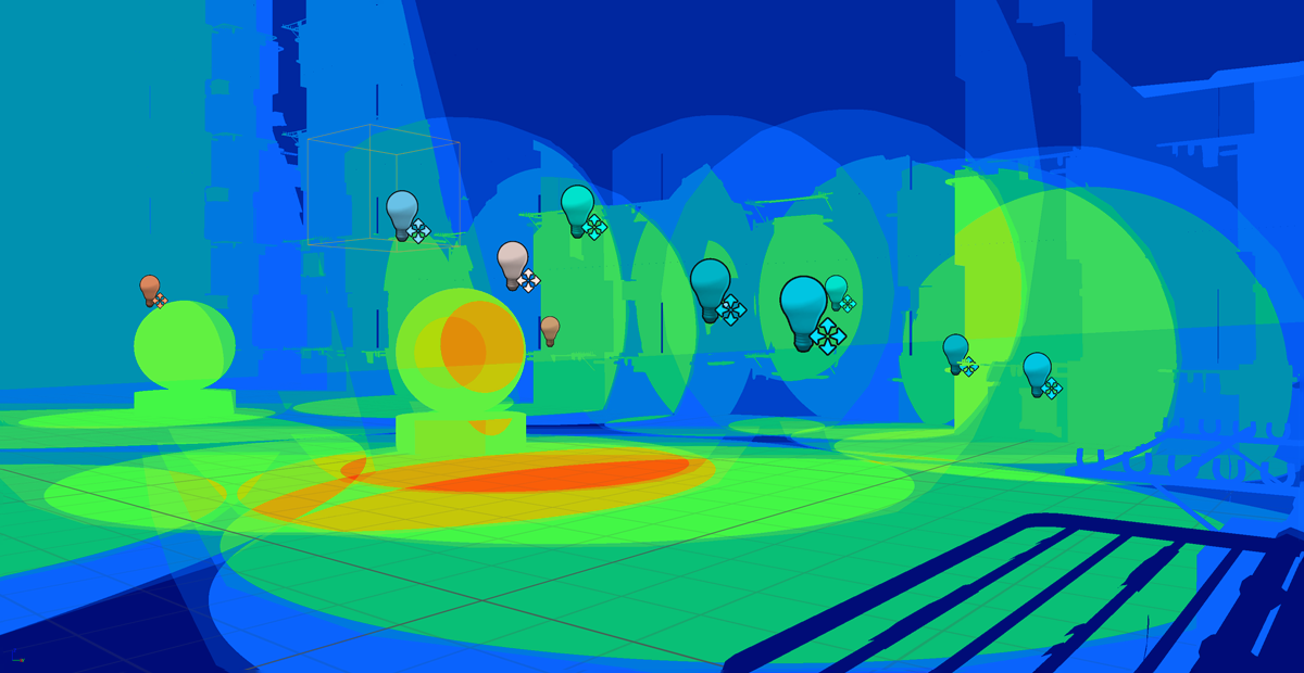
Light Complexity shows us the radius of each particular light. And we can see them overlapping. Let me move this light away… As you can see, this is the area… …that is affected by the light. Okay. Now it should be better. So this is this light’s area of influence. If I copy the light… …you can see how the cost increases in the place where they overlap. That’s because the pixels have to be shaded with two sources. With two sources of lighting. Obviously, more light overlapping mean more troubles with performance. Here is a particularly bad area. So a good place to change some lights to static or just delete them.
Shader Complexity
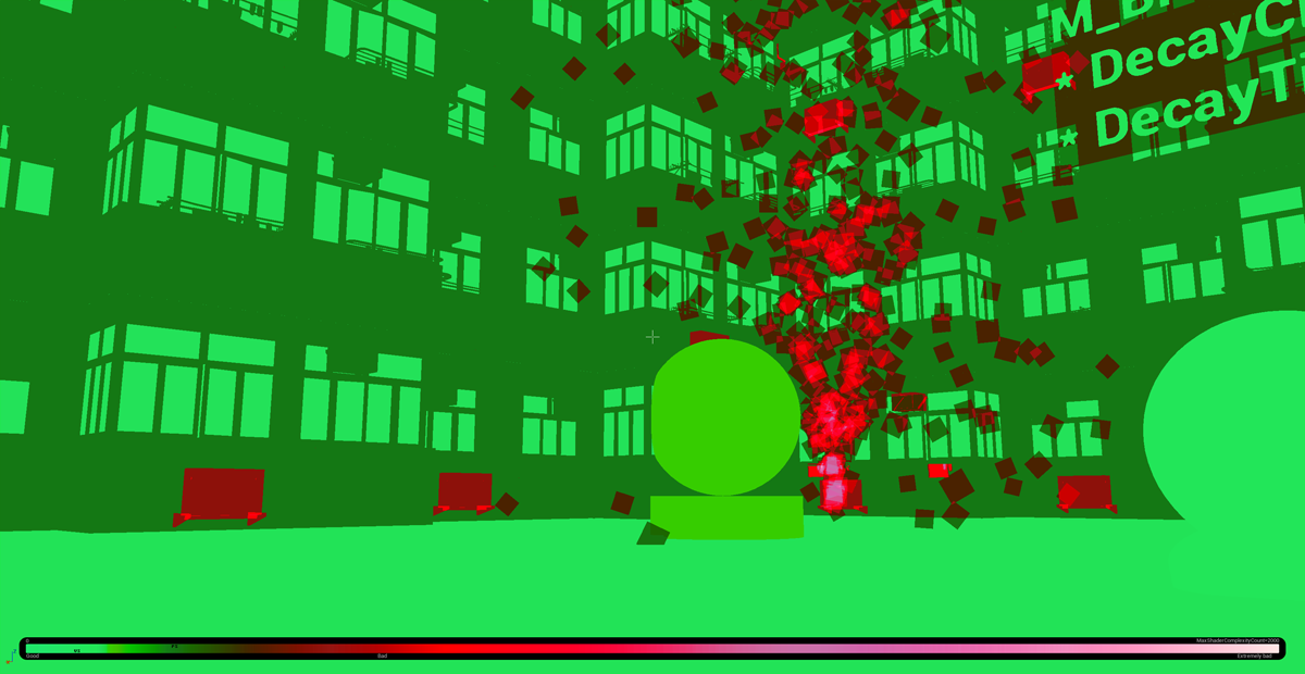
Another interesting mode when it comes to the complexity of rendering pixels is Shader Complexity. Now you can see that this area is very, very bad when it comes to rendering of shaders. That’s because the cost of shading when it comes to translucent objects is not only the closest one but also all the objects behind. So this is a sum of the cost of shading - of all the objects from camera up to the end of visibility. That’s why if we have only some translucent things overlapping, it’s not that bad. But as we go further with the amount of additional planes being blended together, we start to have a problem. As you can see here, when I go back to Shader Complexity, it’s… extremely bad.
Quad Overdraw
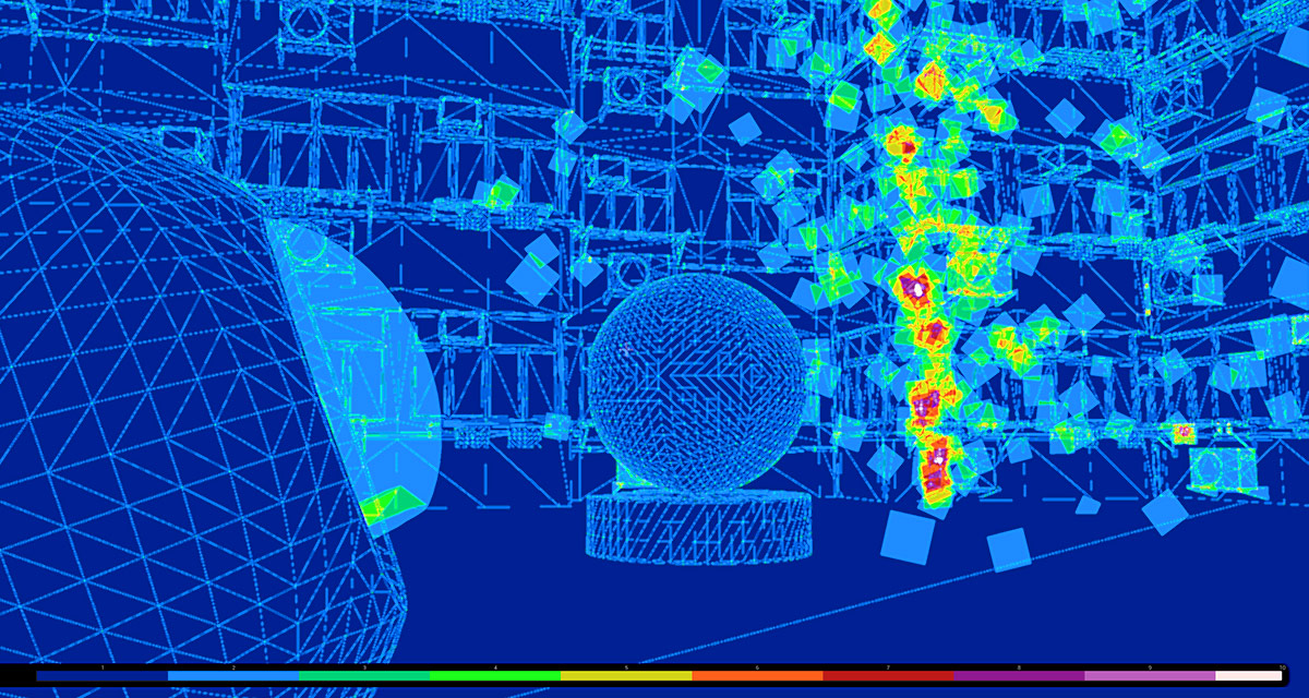
Quad overdraw is the problem that mentioned earlier. As you can see, it shows the general overdraw. Not just the quad overdraw problem. So when we have multiple translucent things in behind each other, it goes all the way to white. But for example, our level of detail settings for the asteroids seems to be set to a bit too high, because we have very small polygons, frequently overlapping each other. This building is very well optimized. Because we have almost no overlapping here. Now let me disable the grass. Come on, grass… Disappeared. Thank you. Currently, the tessallation of the landscape is quite fine. But if you ever have some problem with that, Then there is a thing you can do. Go here to… “Landscape” → “Manage Mode” → the “Selection” tool for components. Select the components that you think have too many triangles and it the “Details” tab, go to “LOD bias” and set for example 1 or 2 or sometimes even higher. And as you can see, the amount of vertices used decreased. This is a very good practice to to lower the amount of triangles in your landscape except for the areas that really matter.
Lightmap Density
When it comes to memory, an interesting optimization view mode is Lightmap Density. This mode shows the size of the actual pixels of lightmaps that will be calculated and stored. So the landscape has quite a low resolution and it’s OK, because the entire landscape is big. And remember that lightmaps are stored for each object separately. Each occurrence of the same mesh will get it’s unique lightmap anyway, because it stores lighting, which is different for all the places in the scene. So if you’re not careful, this can really explode into huge numbers. And the lightmaps don’t have to be too detailed. They can be quite blurry most of the time. It’s better to change your idea for lighting a bit or some smoother shadows then for example to increase lightmap density. Here each module has 32 pixels, I think… no, 64. As I change it, you can see how the density of pixels increases and the color changes through green all the way to red.